
In this tutorial, we are going to cover the process of creating a new object mesh, the textures required for that mesh, and then getting them all into the game using TSR’s Workshop.
Things you’ll need:
- A 3D program. I’ll be using Blender, as it’s free, so anyone can follow along. Current version as of this tutorial is 2.77a.
- A 2D graphics editor. I’ll be using The GIMP. (The GNU Image Manipulation Program.) It’s free, and practically identical to Photoshop as far as features go.
- TSR Workshop. Current version is 2.2.34.
- A Windows operating system, or a Windows emulator such as Parallels Desktop or Bootcamp. TSR Workshop does not work on OS X.
- A working copy of The Sims 4, patched and fully updated.
Please note that I’ve selected Blender and Paint.NET because they are freely available to everyone to use. If you are already familiar with other 2D and 3D programs and are more comfortable with them, feel free to use them.
We will be using a specialized .WSO format, however, and currently there are only plug-ins for Milkshape3D (very old, and not free) and Blender3D. Workshop can handle .OBJ and .FBX as well, but be aware, there are some limitations and different workflows for using those formats that will not be covered in this tutorial.
Blender: Set Up
First things first, we need to get our programs installed and set up. After installing all three programs, we are going to need to get Blender set up to work with the .wso files that Workshop outputs. The first time you open Blender, you’ll see something like this:

Lots of buttons and panels, oh my! Worry not, 90% of these will never be used for our purposes and can be ignored. A lot of working in Blender will actually be using keyboard shortcuts – there are only a couple parts of the interface that we will be using later on.
We’re going to go to File > User Preference. That’ll open this window:

Down at the bottom of that window, there is a button that says “Install from file…” – click on that. That brings up a file browse dialog. There are two plug-ins we need to load up: one for importing .wso files, and one for exporting .wso files.
Browse to wherever you installed Workshop to – the default is C:\Program Files (x86)\The Sims Resource\TSR Workshop\ – and open the “Extras” folder, and then the “Blender 2.74” folder. There will be two files inside, of which you need to import them both. (I believe you have to import them one at a time.)
![]()
After you have imported them both, from the “Add-ons” tab, on the left panel, click on the “Import-Export” button. This will filter the plug-ins so that you only see import/export options. Scroll through the list and find the import and the export for .WSO, and check the box for both of them.
![]()
![]()
Click “Save User Settings” and then you can close the User Preferences window all together. Now to check, go to File >Import and verify you have the option for .WSO. Likewise, check and verify you can export .WSO as well. Okay! Moving on, let’s actually get started!
Cloning in Workshop
Upon opening Workshop, this is the window we are presented with.

Note that your “Recent Projects” will be different, and probably empty at this point.
Workshop needs to be pointed to where the game is installed before you will be able to clone anything, though. It will try to find the game location automatically, although it doesn’t always work. To double check, go to Edit > Preferences > Folders.
In the top heading for “Global Folders,” ensure that the Sims 4 Data is pointing to your TS4 folder in Documents. By default this is C:\Users\*your username*\Documents\Electronic Arts\The Sims 4.
Further down at the bottom of the window, there will be a heading for “Sims 4 Folders” with a “Base Game” entry. This needs to point to where the game is actually installed, which by default is C:\Program Files (x86)\Origin Games\The Sims 4. Click “Apply” if you had to change the paths, and then close that window.
Note that you need to have actually started the game, selected a family and played, and have saved the game after playing before the game will generate it’s complete folder structure.
We’re now going to click on “Create New Project” to get started. This brings up the “New Project” window where you select what kind of project you want to start.

We’re going to choose “Object.” The next window will load up all of the game content – which may take a moment depending on the speed of your computer.
 That brings us to this window, where we can start to filter through the game content to find what we want to make.
If you have the paths set for both TS3 and TS4, you’ll see a heading for both games. Ensure that you are choosing your object from the TS4 heading. If you only have paths set for TS4, then you won’t see anything for TS3.
We’re going to make something classically simple – an end table. Click on the “+” button next to “Surfaces.” The list will expand and show all of the sub-categories for surfaces. Find “End Table” and click on it.
Note that if you click on the actual heading for “Surfaces” (or any other heading, and not just on the “+”) Workshop will start loading all of the items in that category, which may make Workshop appear to be frozen for a few moments while it sorts itself out – depending on the category you’ve clicked on. Some are much larger and slower than others.
Once all of the end tables have loaded, we’re going to scroll through and choose one that looks like it will be a good base for us to start with.
Note when picking a base, compare it to what you want to make and choose something similar in size, shape, and style. Meshes have different “levels of detail,” higher polygon meshes have more levels of detail that you may not always need for a simpler mesh. Likewise, there are “occluders” that cast indoor shadows based on the shape of the mesh, and they are a pain to have to change.
For this tutorial, I am going to pick the “Mega End Table.” Upon clicking on the icon, you’ll get a small pop up listing all of the recolors that exist for that item – you can click on whichever one you want to work from, but I always try to pick one that’s close to what I intend to make.

I’m just going to go ahead and choose the default for now. That brings up this window:

In this window, you can name the project (this is your working title for the item), the actual “Title” (this is what the object is called in the game) and then you can write a description of the item you intend to make.
There are two check boxes as well:
- This is a recolor only: tells Workshop that is just a recolor, so it only clones the needed parts for a recolor and then links it up so that it will show up as a color option on the original item. Obviously, note that you would only choose this if you are making a recolor. You can not edit the mesh on a recolor.
- Add all color options: Does exactly what it says, instead of just picking on color for you to work with, checking this will include all of the available recolors. If you’re going to be making several recolors of your object, it may be useful to have them included in the file to start with. Note, however, that you can always add and remove recolors from the item at any time.
After entering your information and clicking “next,” you’ll get a screen that just says “Finished.” Click the button that says “OK” in the lower right, and your newly cloned object will open.
Please note that it’s considered good practice to include your creator username and where you are hosting your content in the item description, so that people can find it in the game should they have an issue with it and need to contact you, or if they just want to see what else you’ve made, etc.
Once you’ve gotten your item cloned, this is what’ll you’ll see in Workshop:

If you see a big green square, that is simply the ground plane. This can be changed to white (or any other color) in Edit > Preferences > Mesh Editor > Ground Color.
I’d take this opportunity to go ahead and save the file as well. File > Save As, and save it somewhere you can find it. I’d suggest making a folder somewhere for all of the files that will be relating to this tutorial. The file will save as .wrk, which is Workshop’s native format.
The buttons along the top of Workshop pertain to the viewport and what it shows – the first four shape buttons are the levels of detail present in the mesh. This item has three – a low, medium, and high. The 4th “Very High Detail” level is usually reserved for sim-related content like hair and clothing. Objects have three at most, some may only have two, and some may only have 1. You can click on these buttons at any time to see the way the lower detailed meshes look.
Meshes are made of triangles, called polygons. (Or “faces”) The more faces something has, the harder it is for the game to display. The “average” rule is for every tile that your object takes up in game, you can have 1000-1200 polygons in your high detail mesh.
A one tile object should stay under ~1200 polygons. A 2 tile object should stay under ~2400 polygons. Etc. The bigger an item is in the game, the less likely it is to be used all over the place, so higher limits are allowed. (You’re not going to have 5 double beds in one room, but you might have 5 small potted plants, for example.)
Each level of detail for your mesh should have a progressively lower polygon – I generally aim to have the medium detail be ~70-75% of the high detail, and the lowest detail as low as I can possible make it until it starts to look broken.
The next group all either hide or show something relating to diagnostics of the mesh – the first button shows or hides a grid, the second shows mesh normals (a more advanced feature). The third one turns the ground shadow on and off, the fourth one (the round circle) toggles the normal map display (a very big thing in TS4). The gray lines with blue dots changes the display to wireframe.
The button with the gradient and the light bulb makes your mesh transparent (only for Workshop’s display, not in game). The red square toggles the object’s footprint and also shows any slots (more on this later!) and the last one shows any bones that are in the object. (Also, more on this later.)
The “Free” drop down menu relates to the view – in free, you can rotate and view the object in 3D however you want by clicking and dragging. You can also change it to side, top, bottom, etc.
The “View” drop down menu changes between free view, panning, and zooming. Note that you’ll never need to change this, as in “free” view you can zoom by right click + drag, and you pan around by holding alt + left click + drag.
The tri-axis display in the top right corner of the 3D view with the three arrows is so you can tell which way your mesh is facing – each arrow represents a particular axis in 3D.

Y = Up (Green)
X = To the right (Red)
Z = Towards the front of the item (Blue)
(More on these axis later on when we start actually meshing!)
In the big panel on the right side of the screen, there are several tabs – this is where we actually work on our object. These will be covered more in depth as we go.
- The Project Tab: Contains all of the basic information about the item. Name, price, description, etc. There are some categories and tags here as well (you typically won’t have to change them) and lastly some thumbnail icons and color swatches for your item in game.
The drop down box at the top of the Project Tab is where you will find your recolors listed, and the buttons to the right either create a new one, or delete the existing one.

- The Materials tab: Initially blank, the drop down menu at the top contains all of the materials that are present in an object. A mesh can have groups, and each group can have its own material.

Clicking on a material will then open that material so that you can edit the textures within. - The Mesh Tab: The mesh tab contains all of the 3D models that make up the object. This typically includes the mesh for the object itself itself, as well as it’s lower-detail variations, and its indoor ground shadow, and its outdoor sun shadow.
The drop down menu at the top shows you each level of detail that is present:

- The Slots Tab: This tab contains all the extraneous information, such as slots, bones, footprints, etc.

- Lastly, we have the Misc tab, which contains a few other random bits that are of use on certain items.

Lights are only found on lamps, and the masks and cutout options are mostly used on windows and doors, among a few other objects.
The “Lights” heading also contains the “occluders,” previously mentioned, which control the indoor shadow an object casts when placed near a light/window/etc.
So, that sums up our very quick tour around the Workshop interface – we’ll cover more as needed as we progress through this tutorial. For now, let’s actually get started meshing!
Blender: Creating Our First Object Mesh
We’re going to first head over to the Mesh tab in Workshop. At the top, to the right of the Level of Detail menu, there are two buttons – one with a green arrow, and a red arrow:
![]() The red arrow pointing out is the Export button. The green arrow pointing in is the Import button. With the “HighDetail” active, click on the Export button. You’ll want to save it somewhere you can easily find it – preferably in the folder you made earlier for all of the tutorial files.
The red arrow pointing out is the Export button. The green arrow pointing in is the Import button. With the “HighDetail” active, click on the Export button. You’ll want to save it somewhere you can easily find it – preferably in the folder you made earlier for all of the tutorial files.
Ensure the “Save as type:” dialog is set to Workshop Object .WSO and then go ahead and save it – but make sure you give it a name that adequately describes what it is. Something like “Tutorial End Table HD” – HD signifying that it’s the high detail mesh. Upon clicking Save, you’ll get another pop-up asking about what version to use:

Ensure that you have Version 6 – For Blender selected, and then click OK. You can check the “remember for all future exports” if you want, however, be aware that Version 6 .WSO files cannot be imported in Milkshape, should you ever need to use that program. As I actively use both Milkshape and Blender, I leave it unchecked.
Once you click OK, Workshop will tell you the mesh was exported successfully.
Now is also a good time to save your file again.
Let’s switch over to Blender now – although you can leave Workshop open. Here we have the default Blender scene:

There are a few things here that we will not need. To start with, the big cube in the middle. We’ll be using some cubes here in a minute, but for now, this one is just in the way. With it selected, it should be outlined in orange (to select something in Blender, right click on it.) and then press the “Delete” key on your keyboard. You’ll get a little pop-up asking if it’s okay, go ahead and click “Delete” to get rid of the cube.
There are two other things here we don’t need – the first being the light source, which is displayed as the black dot with the circle around it, and the line reaching down to the grid. Right click on the black dot, and again, delete it. The game provides all of the lighting we need.
Lastly, the other item is a camera – depicted as a sideways pyramid with an arrow pointing upwards. We’re not rendering anything from Blender (again, the game does the rendering for us) so you can right click on the camera and delete it. This gives us a nice, clean scene to start with.
Note that if you would like, you can go to File > Save Startup File, and that will tell Blender to open the scene like this every time – no camera, cube, or light to delete. It saves a bit of time when you end up opening Blender hundreds of times over the span of your meshing career!
Let’s go ahead and now import the mesh we just exported from Workshop. To do so, go to File > Import > WSO Mesh to Scene. Browse to your tutorial files folder, and import the .wso file that we exported. (NOT the .wrk file, Blender doesn’t know what to do with a .wrk file!)
You should then see something like this:

Well, that’s, uh, interesting! A bit different than what we saw in Workshop!
What we’re looking at here are three things:
- There is the mesh for the table itself.
- There is the mesh for the ground shadow.
- There is the “skeleton” of the object, showing the bones that are present.
A mesh is just 3D data for the shape of something, that’s why everything is gray. This is normal at this point.
We don’t need the skeleton at the moment, it’s just big and in the way, and Blender doesn’t actually display it correctly, so we’re going to hide it. To do so, look to the top right corner – there is a small window listing everything present in the scene.

 What we want to do is find the skeleton, and toggle it’s visibility. The skeleton is listed as “Armature” and has an icon of a person to the left of it. If you click on it, the word “Armature” will turn white, and the skeleton should become selected in the viewport with an orange outline.
To the right of that, there are three icons: an eye, a cursor arrow, and a camera. Click on the eye. It will close, and the skeleton will disappear from the viewport, but it will stay in the scene for when we need it later. We just don’t want it in our way for now.

Now, if you look at the other items listed in that top right window, there are three mesh groups, designated by “Group 0” through “Group 2” with a triangle outline next to them. That indicates that they are polygon meshes. You can click on each one to see it highlighted in the viewport.
- Group 0 is the big square underneath – that’s the main ground shadow. It will get a texture later on that just makes it a big dark spot.
- Group 1 is four smaller squares, one under each leg of the table. These are also shadows for where the leg hits the ground.
- Group 2 is the actual table mesh itself.
Let’s learn how to move around within Blender!
The most basic task is zooming in and out on the mesh, which can be done with your scroll wheel on your mouse.
If you do not have a mouse wheel, or are on a laptop/tablet without a mouse, you can go into File > Edit User Preferences, and under “Input” there is a checkbox for emulating a three button mouse. You can then use ctrl+alt+ left mouse button drag to zoom.
To rotate the mesh, click your scroll wheel and drag around.
Again, without a mouse wheel, if three-button emulation is enabled, you can alt+left click+drag to rotate.
To pan around the viewport, shift + mouse wheel click + drag.
Without a mouse wheel, if three button emulation is enabled, you can shift + alt + left click + drag to pan around.
Take a moment to get familiar with the controls – they can be a bit awkward at first.
Next up, it’s time to actually start making our mesh. If you look in the 3D viewport, you’ll see a little red and white circle with crosshairs – this is the location at which new meshes will be added. It’s almost impossible to get this where you actually want it, so as long as it’s “near” where you will be creating the mesh, we’ll be okay. Simply left click anywhere in the viewport to move it.
My mesh editing is going to be a bit chaotic and weird, but it’s because I’m trying to show as much of Blender as possible while we work.
We’re going to start by adding a cube that we’re going to turn into the table top. To do so, press Shift+A, and you’ll get the “Add” menu. Choose Mesh, and then cube.

That made the viewport now look like this:

It would appear that we are inside of our cube, because the default size is so large. Zoom out so that you can see the whole cube – it should be selected still (if it’s not, right click on it to select it) and then press “s” on your keyboard. (S is for scale.)
That’ll give you a double-headed arrow attached to the cursor, and a line attached to the center of the selected mesh. Move the cursor towards the center and it will shrink. (Likewise, pull it outwards to enlarge). Once it looks to be about the size of the existing table, left click once.

Here is my shrunken cube, and as you can see, it’s a bit off from the table. That’s okay, we can adjust that.

Using the colored arrows, you can drag the selected item along that axis.
Now, you’ll note that the axis arrows are a bit different than what we saw in Workshop earlier. Blender uses a special axis system, where Z is actually considered “up” instead of Y.
In Blender,
Y = Towards the back of the mesh (Green)
X = Right (Red)
Z = Up (Blue)
Don’t worry about this too much. The export plug-in will automatically flip our mesh around so that it matches up with Workshop. It’s just a bit confusing for the user, because you have to remember the axis you’re working on are different than normal.
Here, I’ve dragged my cube towards the center of the table mesh, and we see that it’s not quite the right size.

If I press “S” for scale again, I can drag it back up a bit so that it’s closer to the right size.

“Right size” you say? That’s huge! Ah, but it is the correct width of the size of the table. It’s just too thick. That’s an easy fix as well. Press “S” again, and then afterwards, press “Z.” This tells Blender that we’re only scaling on the Z axis, up and down. Blender displays this constraint as an infinite line in the color of the axis you are locked to. I can then scale down the thickness of my table top.

The three main controls in Blender are Grab, Rotate, and Scale – each one accessed by it’s first letter as a keyboard shortcut.
As we learned, “S” opens the scale tool.
“R” will activate the “Rotate” tool.
“G” activates the grab tool, which attaches the mesh to the cursor for you to move it.
All three commands can then be altered by pressing the letter of an axis, X, Y, or Z. These commands can be further adjusted by then typing in a number to alter the mesh by that amount.
For example, pressing “S” then pressing “Z” and then typing in “2” will tell Blender “scale on the Z axis by 2” – this would make the mesh twice as tall. This can be done with any of the tools, on any axis, by any amount. “G” “X” “5” would tell Blender to grab the mesh, and move it 5 grid units along the X axis. It’s a very powerful way to work quickly, once you get used to it.
Now that we’ve got a good base for scale to start with, I’m going to drag my table top back off to the side a bit so that I can see what I’m working on without the original being in my way – although I don’t want to get rid of the original just yet.

Now we need to create some legs! With the table top still selected, press Shift+D, which is going to duplicate the table top cube, and freely attach it to the cursor to place where I wish. I am then going to press “Z” to lock it onto the Z axis, and I will move the table down a bit so we can start on the legs.

To get this sized to something more suitable to a leg, we’re going to scale it down to be narrower, but taller, although in a slightly different fashion than we have thus far.
To do anything more than basic scaling, moving, or rotating, you have to go into what is called “Edit Mode” – this allows you to edit the actual vertices, polygons, and edges that are in the mesh.
To switch into edit mode, with the desired mesh selected, simply press tab. This turns the entire mesh orange, showing it is selected.

If we press “A,” it will deselect everything, and our mesh will turn grey. (If nothing is selected, pressing “a” will select all, and if anything is already selected, pressing “a” will deselect it.
At the bottom of the 3D viewport, there is a toolbar full of buttons.

The drop down menu towards the left that says “Edit Mode” is the mode selector. Blender has many modes, but all we need are object mode and edit mode, which we can toggle between with tab.
 Next to that, that single white circle controls how the mesh is displayed. Right now, it’s set to default, which is just a regular solid gray mesh. There are several other modes, such as wireframe and textured. We’re going to go into wireframe mode – you can either select this from the menu, or you can just press “z” on the keyboard.
Once we’re in wireframe mode, you’ll notice that your mesh is now just a bunch of lines and dots. These are the edges and vertices, which control the shape of the faces. Only the faces ever actually get rendered in game, the vertices and edges are just control points for editing the mesh. The darker gray mesh with the orange dot indicates that’s the selected mesh.

Now back up in the 3D view, press “5” on the number pad on your keyboard – ensuring that “num lock” is on. This changes the 3D view between orthographic, and perspective. Orthographic is almost like 2D – think how The Sims 1 looked. We’re then going to press “1” to tell Blender to switch over to “front” view.
Again, if you don’t have a number pad on your keyboard, or are on a laptop/tablet, there is an option in User Preferences under “Input” that will allow you to use the regular number keys in place of the number pad.
5 = Switch between orthographic and perspective 1= Front 3=Right 7=Top 9=Bottom
4=Rotate view left 6=Rotate view right 2=Rotate View down 8=Rotate view up
From the front view, press “B” on the keyboard. This enables “box selection” – you can just drag a box around what you want to select. We want to just select the bottom vertices of our cube:

We had to switch into wireframe mode for this to work, otherwise if it were solid, we would only be selecting the front two vertices. By doing this in wireframe, we will also get the back vertices through the mesh.
Then we’re going to press “G” for grab, and then “Z” to lock it to the Z axis, and drag it waaay down:

Now press “A” to deselect. Press “5” on the number pad to switch back to perspective, and then rotate the view so you’re looking at the mesh from an angle:

Head down to the bottom toolbar again, where the mode selector and such was. There are three buttons towards the middle: one with a dot, one with a line, and one with a square – these represent different selection modes. The default is vertex, but we can change it to edges and/or faces as well. We want to change it to face.
![]()
From there, you’ll see the mesh will now have a small square in the center of each face. Right clicking on that little square will select that face. We want to select the top face:

Press “G” again, followed by “Z,” and then drag that top face waaay up.

Press “A” to deselect. Press “Tab” to get out of Edit Mode and back to Object Mode. Then press “S” for scale, and scale our long cube down to be the appropriate size for a table leg.

At any point, you can press “z” to switch back to solid display mode if you want, so we can get a better idea of what the table is looking like.
My table has the leg going a bit below the grid (which, in game, is the ground), which we don’t want. I am going to right click on the table top to select it, and hold shift, and right click on the table leg as well so that I end up with them both selected, and then I am going to drag it up just a bit so that the bottom of the table leg is sitting on what will be ground level in game. This also results in my table being a bit higher than the original, but that’s all right.

I am then going to select just the table leg, and using the colored arrows, drag it over to one of the corners where an actual table leg would go. Switching to orthographic view, and using the side views is enormously helpful at a time like this to get things lined up.

After that first leg is in place, I am going to select it, press “Shift+D” for duplicate, and then “x” to lock it to the x axis, and then drag it over to the other side of the table.
From here, I am going to hold shift and right click to select the other table leg as well, so that they are both selected. I am then going to duplicate (Shift+D) both of them at the same time, and press Y to lock them to the Y axis, and then move them both to the back half of the table.

That looks much more like a table, now! You know what, though? I like the shelf that the original had underneath. Let’s select the table top, duplicate it (Shift+D), and move and scale it down so our table has a shelf underneath as well.

Wooh, that’s a pretty decent table! However, the proportions seem a bit off to me. If we hold shift and right click on each part of the mesh to select all 6 parts, we will then push “Ctrl+J” for “Join,” and this will merge all of the parts of the mesh together into one. If we go into edit mode now (tab) then we can see we are editing the entire thing at once.

Let’s change back to vertice selection mode using the buttons on the bottom toolbar:

Then, go into wireframe mode with “Z,” then press “B” for a box selection, and select the entire top part of the table:

I’m going to move it down, as I want this table to be a bit lower than the original, not higher. I think it looks more proportionate this way.

Here’s our mesh now, in comparison with the original.

Since TS4 works very well with levels of detail, let’s go on and fancy our mesh up a bit. Right now it’s nothing but cubes, and that’s as simple as it can get. What’s the point of having levels of detail if we’re not going to use them?!
Notice how the original table has a highlight along the top that ours does not. That’s called a bevel. It’s great for making things “catch the light” so to speak. Let’s add that beveled edge to our table top.

Select the table mesh, and go into edit mode. Change the select mode to faces, if it is not already. Select the top face of the table. Press the “W” key, which opens the “Specials” menu. In this menu, there is an option for bevel. Choose it.
This attaches a cross hair to the cursor, that is then attached to the center of the selection, much like the scale tool. You can pull in or out to adjust the size of the bevel that is being applied. We want just the slightest bit of beveling:

I am going to repeat this on the top face of the bottom shelf as well. Our table now has a nice little highlight on each shelf.

Now, this next part may seem a bit out of place in the workflow, but we need to think about our meshes’ normal map, and what we can put on it. In order to do that, you need to know what a normal map is.
A normal map is a texture that the game reads, and it adjusts the way the light hits the object to create highlights and shadows from geometry that isn’t really there. It’s a very powerful technique, which allows for an incredible amount of detail to be added to our object that we couldn’t reasonable put on the mesh itself.
Normal mapping works best for physical texturing and small details – since it just copies the lighting, not the physical shape, anything too drastic looks fake.
An example of how a normal map works, from Wiki:

On the left you have the physical mesh. In the middle is the normal map. On the right, you see the normal map applied to a plane, where only the lighting is copied. With drastic shapes, such as the pyramid, it ends up just looking… odd. It’s much better used for smaller details, where the lack of a physical shape isn’t a problem:

The left side has a normal map applied, while the right side is what the mesh actually looks like.
Thinking about this, you have to plan out what you can put on the normal map and what you should put on the mesh itself. The fewer details that are on the mesh itself = the better it will perform in game. Many people have lower end computers, and you want to make sure your content will work for everyone.
In thinking about our table, there’s not too many kinds of small details that we could add – and you don’t want to add things simply for the sake of them being there, or your design just becomes a mess. I’m thinking we’ll keep it simple, and just add some screws in a few places. Now, there are a couple of ways we can go about this. The best way depends on the detail of the mesh in question.
- Create a super high detail mesh featuring all of the little bits and pieces we want, then copy the lighting over to a normal map on a slightly lesser detailed mesh. That slightly lesser detailed mesh then becomes the HD mesh in game, combined with the normal map, to represent the super high detail mesh made originally. If that seems super confusing: The actual, full HD mesh ultimately gets discarded, while we just copy over the details from it onto a normal map on a lower detail base mesh, which actually becomes our HD mesh in game. Then you reduce that base mesh for each level of detail you need for your object in game. The original fully detailed mesh is just a reference to create the normal map.
- Create the HD mesh, and actually use it in the game as the mesh for the high level of detail. Then copy the lighting details over to a normal map for the lower levels of detail.On a mesh that has hundreds of thousands, or even millions of polygons, you obviously can’t use that as your HD mesh – the game, nor Workshop, will not tolerate it. For a mesh that is particularly low poly, it may be acceptable to actually the full HD mesh in the game.
To decide what the most appropriate options is, we can check and see how many polygons our table is so far in Blender.
Select the table mesh, and go into Edit mode either via the drop down menu on the bottom of the 3D viewport, or by pressing “tab.” Then, in the top right of the widow, there is a section with several different statistics:
![]()
This display will show stats for the entire scene, if in object mode, or for just the active object if you are in edit mode.
Verts refers to vertices (aka “the dots”), edges are obviously edges, faces refers to “quads” — you’ll notice our mesh is currently made up of squares (aka “quads”), not triangles (aka “polys” or “polygons”) — and tris refers to what the mesh will be one converted to triangles. (Workshop automatically converts everything to triangles upon import.) So, at this point, our table is only 88 polys by Workshop/TS4 standards. That gives us tons of room to add a little bit of embellishment, so we’ll go with option #2 from above. Add some details to the mesh, use it as the HD mesh, and then copy it to a normal map for the lower levels of detail.
So, with all that being said, let’s continue adding some details to our mesh. I’m going to add a few screws – one going through the table top into each leg, and then some down on the legs that would be holding in the shelf.
Details, details, details! While it is entirely possible for such a table to be made with all of the screws/hardware/etc hidden, I think it makes for more interesting content when you can actually see the details. ALWAYS keep in mind how something would be actually constructed in real life. It’ll make your content much more believable.
Back in Blender, to simulate what looks like a screw, we’re going to add a sphere. To do so, press Shift+A, then go to “Mesh” and choose “UV Sphere.”
There are two sphere options in Blender, UV Sphere and Ico Sphere. UV Sphere is a sphere made out of “quads” – aka squares. An Ico Sphere is made out of triangles. There is nothing wrong with using either one of them, however, the quad-based UV Sphere is generally much easier to actually work with, so that’s what I always use.
Once you have your sphere added, you’ll see it’s quite large, and it’s blocking everything else:

First, notice all of those little squares that are making up our sphere? For the size it’s going to be on the mesh, we really don’t need that many faces. In the window to the bottom left corner, you’ll see the “Add UV Sphere” window with a few sliders. We’re going to use these to adjust the level of detail for this sphere to something more reasonable.
“Segments” is how many vertical divisions there are around the sphere.
“Rings” is how many horizontal divisions are going around the sphere.
“Size” is, well, just the size of the sphere. This can always be adjusted later just by scaling the mesh.
I’m going to use 12 segments, and 10 rings. That gives me this:

Higher values help things look more rounded, but at a small size, you can get away with much, much lower detailed meshes.
With the sphere still selected, press tab to go into edit mode. Press “A” to deselect everything. Press “5” on the number pad to change to orthographic view, and then press “1” to go into front view. Press “Z” to go into wireframe mode. Lastly, press “B” for a box selection. We’re going to select the bottom half of the sphere:

Press “Delete” and then in the menu that comes up, choose “Faces.” That will delete the faces we have selected, leaving us with half of a sphere.


Press tab to go back to object mode, and then we’re going to scale this waaaay down tiny using the “s” key. I also flattened it out a bit, by scaling it down on the Z axis as well as overall. I’ve also moved it into position on top of the table where one of the legs are by dragging it with the arrows.

Now there’s a small problem; we can still see all of the individual squares that are making up this screw. That’s no good! It’s an easy fix, however. With the screw selected, on the left side of the screen there is a “Shading” heading with two options – smooth and flat. You guessed it, we’re going to click “smooth.” Only on the screw, though! We don’t want to smooth out the table itself since it’s made out of wood; we want to keep the hard edges it has.
Now there is one other thing I’m noticing – if I go into edit mode on the screw, the “tri” count is currently at 108 – for something that’s going to be the size of a dot, that’s a bit high. Especially considering that we’re going to have a total of at least 8 of them. Let’s reduce that triangle count a bit!
With the screw selected, tab into Edit mode. On the bottom toolbar, change the selection type to “edges.”
![]()
Then right click on any of the edges that are going “around” the screw, horizontally. (Not one of the ones converging at the top point.)
I’ve selected this one:

Now again, on the bottom toolbar, there are some menus on the left side. Go to “Select.”
![]()
Then choose “Edge Loops” up near the top of the menu.

That then automatically selects that entire “loop” – all of the rest of the edges connected to the one we selected.

With that loop selected, press “Delete” on the keyboard, and on the menu that comes up, choose “Dissolve Edges.”
“Dissolve” is a bit fancier than just deleting the edges. If you delete something, it disappears, along with everything else that was relying on that component’s existence. When you dissolve something, it removes whatever you had selected, but then instantly rebuilds the mesh as if that part you had selected had never existed.
That entire loop we had selected is now gone!

Along with it, the poly count dropped down from 108 to 84. I’m going to repeat that process with the next middle edge loop:

With that second loop gone, now the poly count drops down to 60 – nearly half of what it was originally. Much better.
Tab back out to Object mode, and with the screw selected, press Shift+D for “duplicate,” and then press “x” to lock it to the x axis, and then move it over to the next leg.

Select one of the screws, hold shift, and select the other. Then with them both selected, Shift+D to duplicate them both at the same time, then press “Y” to lock to the Y axis, and move the pair back to the other two legs.

Now for the screws on the legs themselves down by the shelf, I’m going to select the front two screws, and press “Ctrl+J” to join them together into one object. Then press “Shift+D” to duplicate them. Press “Y” to lock them to the Y axis and move them out off of the table a bit. To rotate them around so that they will be flat against the table legs instead of the table top, press “R” for rotate, then “X” to lock the rotation around the X axis, then type “-90” to rotate them negative 90 degrees, which ends up rotating them forward towards us.

Grab the blue arrow and drag them down to where the lower shelf is, then grab the green arrow and move them back up against the surface of the legs.
Tip: switching into orthographic mode (5 on the number pad) (in wireframe – “Z”) can make lining things up a lot easier from the front (1 on the number pad) and side (3 on the number pad) views.

With the front screws selected, I am going to duplicate them again, lock them to the Y axis, and move them back to the rear legs of the table. Then press “R” for rotate, “X” to lock the rotation to the X axis, and then type “180” to rotate them 180 degrees, so they are facing the opposite way.
And with that, our mesh is finished! It’s still nowhere near game-ready, though! Next up, we still have to adjust the shadows to fit, as well as complete the UV mapping, the levels of details, bone assignments, and creating all of the textures.
Let’s move on to getting this thing mapped out!
UV Mapping
UV mapping (also referred to as just “mapping,” a meshing being “mapped,” etc.) is the process of taking our 3D model and cutting it up and laying it out flat onto a sheet so that we can color on it – almost like a coloring book! We’ll be using textures rather than just flat colors, though.
The first step we need to do is combine all of our parts into one mesh. At this point, that just means selecting the table, holding shift, selecting all of the screws, and then pressing “Ctrl+J” to joint them together. (I find that selecting meshes can be easier in wireframe mode, at least for overlapping and small bits.)
To get started with UV mapping in Blender, we first need to open the UV window. This is a rather odd process compared to most programs, but quite easy once you get used to it.
Hover your cursor over the bottom edge of the bottom toolbar, anywhere, until you see the double-headed arrow appear.

Right click, and in the menu that comes up, choose “Split area.”

Move the cursor up into the 3D viewport, and a line will attach itself to the cursor. This is the line that shows you how big your window is going to be. I usually go for somewhere in between ½ to 1/3rd of the window:

Once you click, the window will split in half where you placed the line.
You’ll then have two 3D views.

Look to the bottom left of the right window (the new one that we just made) and there is a small button with a white box and some arrows:
![]()
Click on this button.
In the menu that comes up, choose “UV/Image Editor”:

In the resulting window, you’ll just have a blank grid.

In the 3D view, with your mesh selected in Object Mode, find the menu on the bottom left toolbar that says “Object”:

Go to Apply > Rotation and Scale.

This is a crucial step for UV mapping. When we make a cube, Blender is aware that it’s a cube (or any other shape). However, Blender is NOT aware of what we’re doing to change the shape of that base mesh – we’ve stretched and rotated and scaled just about every part we’ve made so far. Applying rotation and scale tells Blender, “Hey, we’ve made changes! Look!” and Blender then updates it’s internal information to match the adjustments we’ve made to the mesh.
If we didn’t so this, when we try to map it, Blender would create a map based off of the original shapes we made (cubes and spheres) and it would be a disaster to work with, since none of those shapes still exist – the map it would make would no longer fit the mesh.
Let’s actually start making the map, now. With the table selected, tab into Edit mode, and if it isn’t already all selected, press “a” to select all. In the right grid window, you’ll see some vague white shapes appear – that’s the UV map. It’s just not a usable map, yet – we have to remake it to match our mesh.

In the 3D view, press “u” on the keyboard – this opens the UV mapping menu. The first group of options are all automatic mapping options. The rest are all manual mapping options. We could lay out our mesh face-by-face manually, but that is a very slow and unpleasant process. Since we just updated Blender to know the new sizes, shapes, and rotations of our mesh, we can tell it to do the mapping for us!
In the UV mapping window, we want to select the “Smart UV Project” option. That will make the following dialog appear:

We’re going to leave most of these options alone – they work 99% of the time – the only one we need to change is “Island Margin”. Island margin is the space between the faces on the UV map – it’s good to leave 3 or 4 pixels between them to prevent any accidental edges from showing up/overlapping in game. After upping the margin, click “OK.”
Over on the grid window, you should now see lots of various rectangles/squares appear:

Each square on the UV map correlates to a face on our mesh. If you go back into the 3D widow and deselect everything by pressing “a,” you’ll see the UV map will no longer be visible.
If you change the select mode to faces, then you can click on a face on the mesh, and the corresponding face on the UV map will appear.
![]()

Our entire mesh has automatically been flattened out by Blender, but it’s not very logical to us humans. We’re going to make some revisions to it and rearrange the parts so that we can easily work with it.
First things first, let’s collect all of the faces for the table and make sure they are together. We can organize them by what they are, i.e. the table top can all be together, the legs can go together, and then the shelf faces can all go together as well. The screws will all go together off in a corner by themselves.
This makes it easier to know what is where when we actually start making the texture, and makes it a lot easier for recolors, if someone wants to, say, make the legs a different color than the top and the shelf.
So, Blender has this neat feature that lets you hover over a part of something, and then automatically select the entire thing by pressing “L.” I’m going to hover my cursor over the table top and press “L” – and that gives me this:

Here we can see that the table is spread out. The top and bottom of the table top are together, but the side faces are off by themselves. We’re going to put them all together. Hover over the UV window, and press “A” for select all. (All of the same keyboard shortcuts work in the UV window as well as the 3D view!) Then press “G” and just move those faces off of the grid somewhere by themselves.

Moving around in the UV window is similar to the 3D view – press the middle mouse button and drag to pan around, and scroll wheel to zoom in and out.
Next, we’re going to repeat the same thing with the bottom shelf. Press “A” to deselect the table top, then hover over the bottom shelf and press “L.” Move the cursor over onto the UV window, press “A” to select all of the UV coordinates, and then press “G” to grab them and move them off to the side somewhere by themselves. Again, you’ll notice that the top and bottom of the shelf are together, but the side faces are off on their own.

Also note that when you press “L” to select something, it always acts as if shift is being held down – the selections will just add together unless you manually deselect everything in-between each selection you make.
With that in mind, deselect the bottom shelf, then hover over each of the legs in the 3D view, and in turn, press “L.”

The legs are scattered all over the grid. Press “G” and grab them and move them off by themselves as well.

With this being done, I have the table top up off the top of the grid, the shelf is on the left side, the legs are underneath, and by default, that left the screws behind on the main part of the grid.
Speaking of the screws, if we look at their UV coordinates, there are some round bits that are fairly obvious as the tops of the screws.

However, there are also some other random square bits that are not so easily identifiable.

What Blender has done, is since the top of the screen was mostly “flat,” it put all of those faces together since they are facing the same way. The last edge around my screws were sideways enough that Blender decided they are facing a different direction, so they get mapped by themselves. This is slightly less than ideal, so we’re going to remap the screws real quick.
Deselect everything on the mesh, and in turn, hover over each screw and press “L” to select them. We want to end up with all 8 of them selected. Once all of the screws are selected, we’re going to press “U” in the 3D view, and this time we are going to choose “unwrap.”
Unwrap does just what it sounds like it does – it tries to unwrap and flatten out the mesh, almost like if you were taking the fabric off of something like a cushion or a pillow. It generally only works on “open” things that are shaped in such a way that they can be flattened as one piece.
There is a way you can tell Blender how to cut up a full mesh to unwrap it – but that is generally reserved for more organic things, and is a bit out of the scope of this tutorial.
After unwrapping the screws, you’ll now see this:

The UV coordinates for the screws are each now all one piece – much easier to work with! We just need to scale them down to a more appropriate size. UV coordinates should stay in proportion to their mesh. Smaller parts can be made larger on the UV map to make them easier to texture, but also keep in mind the scale of the mesh in question versus the size of the texture that you are giving it. I could make my texture for one of the screws 512×512 pixels, but that’d be ridiculous considering the screws are going to be seen in game at typically something like maybe 5×5 pixels on screen.
Using the “S” key, I’ve scaled my UV coordinates for the screws down quite a lot, but I’ve left them big enough that I have room to texture them, as I want them to have the typical “+” that is often found on the head of a screw. Here you can see how big I left the screws in comparison to the table top:

I’m also going to rearrange the screws, by deselecting them with “A” and then, one at a time, hovering over them and pressing “L” to select them, and then “G” to grab, and I’m going to line them all up.
Note that “L” in the UV editor does not “add” the selections together like it does in the 3D view. You have to hold shift if you wish to select more than one thing at a time this way.
Here I’ve lined up all of the screws along the top corner:

Next, I’m going to move down the table top and get all of those piece grouped together. I’ve placed the top surface of the table right under the screws, and under that I’ve placed the bottom face of the table top. Since the bottom of the table top is probably never going to really be seen, I’m going to scale it down to save some texture space for other pieces. I don’t want to scale it down too much, nor do I want to delete it completely, but it certainly does not need the same amount of texture detail that the top will. I’ve placed the sides of the table right next to the table top.

Next up, let’s move the shelf over. I am going to scale down the bottom side of the shelf just like I did the bottom of the tabletop – no one is going to be able to see under the shelf. I’m placing the smaller underside of the table under the other smaller face, and placing the larger top of the shelf right under the top and sides of the table top. The sides of the shelf are going right along side of the top again.

Note that Blender has automatically rotated all of the narrow faces so that they are running vertically. This makes it easier when you start creating the texture, as any directional pattern (such as wood grain) will all be running the same direction, that way we don’t have to stop and rotate everything ourselves.
Next, I am going to pick up all of the little squares (which are the top/bottoms of the table legs) and line them up along the bottom of the grid. Note that the top of the legs are right up against the table top, and as such, they will never be seen.

These faces can be deleted from the mesh entirely by selecting the face, pressing delete, and then choosing “Faces” from the menu that comes up. That will leave only 4 squares (the table leg bottoms) and will free up some room on our texture. Lastly, I am going to take all of the long vertical faces for the table legs and place them on the right side of the UV grid. Once I have everything on there, this is what my UV map looks like:

There is still some empty room. You can select everything and scale it up just a tiny bit, and then rearrange it all to fit again if you want to have a bit more texture space to work with. Its good practice to minimize the amount of empty space left over at the end, but not mandatory.
Here is my final UV map, with everything scaled up just a tiny bit for a tighter fit:

With the UV map completed, let’s move on! We need to check out UV map for scale and distortion – we don’t want any parts that scaled too big/small, or twisted or stretched etc. To do so, find the “Image” menu on the bottom toolbar of the UV window – and then click on “New Image.”
In the dialog that pop up, change “type” to “Color Grid” and set the size to 1024×1024.

You can set the size to something smaller or larger at this point. This isn’t going in the game, it’s just for us to take a look over our mesh and make sure a texture it properly applied to it.
That test grid should then give you something that looks like this:

To see it applied to our mesh, hover over the 3D view and press “Alt+Z” to change the view to “textured.” We now see this:

This test grid allows you to look for anywhere the image is not appearing “cleanly,” and the numbered coordinates are a quick reference point. If I see the corner at E1 is distorted, I can quickly find E1 on the image in the UV window to know where I need to adjust my UV coordinates.
In this case, our mesh looks good. Nothing is distorted or displaying incorrectly, so we can move on to making our own textures!
Baking a Multiplier
The first thing we need to do is generate what is called a multiplier. If you ever made anything for TS3, the concept is the same. It’s just a grayscale image that has shadows on it to add some realism to our mesh and texture. Luckily for us, Blender can generate these automatically!
We’re going to use a process called “baking” to create our multiplier. (And later on, our normal map as well.) During this process, Blender calculates how light will hit will our mesh and where shadows would occur at – not direct shadows, just some subtle ambient shading. (Direct lighting would be bad, because you never know how someone is going to light a room once in the game.)
To start the process, we need to tell Blender what we want to calculate the shadows with. We only want it to create shadows for our new table mesh – not the original table, nor either of the original table ground shadow meshes.
To do so, go to the top right window that lists all of the objects in the scene:
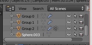
Group 0, 1, and 2 are the original table parts. “Sphere.003” is my custom table mesh – it’s using the name “sphere” because that was the last type of mesh we added.
Notice the icons off to the right side of each side. The eye icon makes it so that we can or cannot see that item. The cursor icon makes it so that we can or cannot select that item. The camera item makes it so that Blender itself can or cannot see that item.
Find the items in the list “Group 0,” “Group 1,” and “Group 2,” and then click on the camera icon for each one. It will turn a faded out gray color. This now means that Blender will ignore these objects in all of its rendering calculations, including baking the multiplier for us.
With the table mesh selected, go into edit mode and select all. Go back over to the UV window, and open the image menu. Choose “New Image” again, and give your soon-to-be multiplier a size.
For reference, a 1×1 tile in the game is 256×256. Therefore, in tile-to-texture area ratio, our table top is slightly smaller than one tile, therefore it should take up slightly less than the 256×256 pixels on the texture. With that in mind, if we consider the top left corner of the image to be 256×256, our full image should be 512×512.

Note that texture sizes all have to be a multiple of 2: 2, 4, 8, 16, 32, 64, 128, 256, 512, 1024. 256×256 is a common size for small items, 512×512 is standard for normal items, and you can use 1024×1024 for large items, or items with a lot of little parts and lots of details.
While on the new image dialog, ensure that the type is “blank” and that the “alpha” box is checked. That will give you a plain black image.
In the bigger main panel to the right side of the interface, find the small button that has the globe icon on it.
![]()
Upon opening that panel, if you scroll down a bit, you’ll find a heading called “Ambient Occlusion” – this is the type of shading we will be giving our object on the texture. Check the box to the left of the words “Ambient Occlusion.” The settings that are grayed out will come in, we’re going to leave them at the default of “Factor: 1” and “Add.”

Scroll down a bit further, and there is another heading called “Gather.” Check the box to the left of it as well. In the settings that appear, the only thing we want to change is the “Samples” Value. This controls the amount of grain in the resulting multiplier.
A low value will result in a lot of grain, while a higher value will result in a much smoother texture. TS4 likes to compress things into oblivion, however, so having a texture that is too smooth will end up getting compressed to the point the game renders it with faintly colored stripes if there isn’t enough texture for it to “latch on to,” so to speak.
A lower value will also complete the baking process much faster than a higher value. If you use too high of a value, it will not only take significantly longer, but if you have a lower-end computer you could end up crashing Blender as well.
I’m going to set my sample value to 12. Leave all the other settings at the default.

From there, go back to the first tab, Render – the button with the camera icon.
Scroll down the panel until you see the “Bake” heading, and expand it.

On the menu for “Bake Mode,” change “Full Render” to “Ambient Occlusion” since that is all that we want for the shadows. Check the box for “Normalized.” (This tells Blender to create our shadow texture with a range of white-to-black. Non-normalized is gray-to-black. White to black gives literally twice the number of values our shadows can have.) Lastly, lower the “margin” value down to about 4. (This is how many pixels Blender will fill in over the edge of the UV coordinates. This helps ensure that you don’t get any strange unshaded edges around your mesh when zoomed out in game.)
Lastly, go ahead and click on the “Bake” button. As long as the table mesh is currently selected, you should see it start to fill in the UV map. This may take some time depending on your computer’s power and the number of samples you have set. Here’s my result:

Back in the 3D view, if you press “Alt+Z,” it will switch the viewport over to textured mode and you can see our shadows applied to the mesh:

(Note that anything that doesn’t have a texture assigned to it, such as the original ground shadow meshes and the original table, will just show up pure white.)
Here’s a quick test – zoom out on your mesh quite a ways, and see if you see anything strange show up around the edges of your mesh.
On mine, I don’t have to zoom out very far before the edges turn black:

This is due to something called “mipmaps.” In a lot of 3D applications/games (such as Blender and TS4), the program switches to a smaller resolution version of the texture as you zoom out, to help use less resources. (There is no point in displaying a 512px texture on something that is only showing up on the screen at 50 pixels, for example; the majority of the texture would be wasted.)
UV coordinates are automatically resized to match the size of the texture applied to them. When an image shrinks, it loses detail – a 2px line at half the size becomes a 1px line, etc. This results in the UV coordinates being just a tiny bit too big, and thus we see the exposed black edges.
This can fixed simply by increasing the margin value. For me, doubling it to 8 fixed the issue.
Now that we have that sorted, we need to actually save our multiplier.
In the UV/Image Editor window, go to the “Image” menu on the bottom toolbar, and choose “Save As Image” (or you can press F3 as a shortcut.)
This will then open Blender’s version of the save file dialog. Browse to where you are saving all of the tutorial-related files, and save the image with a name that you can recognize. The default file settings are fine, and they should be set as follows:

We want to ensure the format is set to be PNG, and set to RGBA. The “A” in RGBA is alpha, which enables the background of our multi to be transparent wherever there isn’t any data.
We’re done with what we’ll be using as a multiplier now, let’s move on to creating our normal map.
Baking a Normal Map
Before we can start on our normal map, we need to create the lower levels of detail for our mesh. Let’s first do so by selecting our table mesh, and dragging it over so that it’s in place over top of the original table. An easy way to ensure our mesh is centered is to, with the mesh selected, go to Object > Transform > Origin to Geometry. This will move the control arrows to the absolute center of the mesh, so you can simply line it up with the center of the grid to center the mesh. (Easier in top-down orthographic view: 5 on the number to switch into orthographic view, then 7 for top down view.)

In the top right window that lists all of the objects present in the scene, find the one that is the table – for me, it’s “Sphere.003.” It may be different for you depending on what base meshes you started with and in what order you combined them.
Right click on the name of the mesh, and choose “Rename” and give it an easy to recognize name for now. I’m going with “Table HD.”
With the HD mesh select, press Shift+D to duplicate the mesh, and then immediately click without moving the mouse to ensure that the duplicate is in the exact same location as the original. That gives me “Table HD.001” which I am going to rename to “Table LD.”
Things are starting to get rather crowded with so many meshes all in one spot. In the outliner window, click the eye icon for each mesh except for the new LD. This should hide everything else:


With “Table LD” selected, go into edit mode. We’re going to make a few edits to remove all of the detail that we can bake our normal map with the most amount of detail.
A normal bakes all of the details from one mesh to another mesh, using the differences between them as a guide as to what ends up on the map itself. Whatever is present on the HD mesh but is missing from the LD mesh will end up on the map.
We want to remove all of the excess detail, so let’s start by removing our bevels. Change the selection type to “Edge” using the buttons on the bottom toolbar, change into wireframe mode (“Z” on the keyboard) and select all four corner edges of the bevel that are hidden within the legs. (Hold shift to select more than one at a time.)

Once all four are selected together, press “Delete” on the keyboard, and then in the menu that comes up, we’re going to choose “Edge Collapse.” That collapses those four edges we had, and since they were what was holding up the top beveled face, that bevel will disappear.

However, if we go back to textured mode (“Alt+Z”) then we see we have a bit of a leftover shadow from where that bevel was:

Very minor, but still, let’s fix it. Select the top face of that bottom shelf, press “G” for grab, then press “Z” to lock it to the vertical Z axis, and then you either drag it up, or for such a small amount, you can also press the up/down keys to nudge it up and down. I pressed the up arrow 5 times:

Now press “S” for scale, and drag out that top face until it lines up with that shadow edge:

The shadow isn’t perfect, since it follows the beveled edge at a 45 degree angle. But at such a small scale, that’s not even noticeable when we look at the table a whole:

Next, to remove the bevel around the top edge, select one of the four edges around the bottom of the bevel:

Then go to the Select menu on the bottom toolbar, and choose “Edge Loops” to select the entire ring around the table. Press “Delete” and then “Dissolve Edges.” The table top will shrink microscopically just like the shelf did. However, when you “dissolve” something, it adjusts the mesh and the UV map to compensate for what you’re removing. If we scale the table top back out, then the shadows underneath of the screws will move as well.
UV Coordinates “attach” the texture to the mesh. If you distort/stretch/move the mesh in any way, the texture will distort/stretch/move accordingly.
The difference in size is so slight that we’re not going to worry about it. The last bit of detail that we can remove is the screws. Rather than remove them, though, we’re just going to remove all of the edges on the top that we can. (Removing them would leave black shadows behind from where under the screws are.)
Go into edit mode for the LD table mesh, and go into edge selection mode. Select one of the edges in the ring around the center of the screw:

Go to the “Select” menu on the bottom toolbar, and then choose “Edge Loops.”

Press delete on the keyboard, and choose “Dissolve Edges.” You can also press “Ctrl+Delete” as a shortcut.

I’m then going to repeat that with the last edge:

That just leaves a cone shape that looks something like this:

That knocks the poly count down to 12 for this little piece, versus nearly 60 originally. I am going to repeat this across all 8 of the screws, which total nets us close to 400 polygons less. That leaves enough detail that you can see the screws, but we’re going to make the normal map replace the smoothing we just took away.
With the mesh reduced all of the way, we’re going to go ahead and now bake our normal map!
To start, select the low detail table mesh, and go into edit mode. Press “A” to select everything if it isn’t already. In the UV window, go to Image > New. Make sure that the size is the same as your multiplier from earlier, and then click okay.
Then, under the “Render” panel – the first tab on the right with the camera icon – find the “Bake” settings again. This time, we’re going to change it from “Ambient Occlusion” to “Normals.” That will change the window to have the following options:

“Normal Space” should stay set to “Tangent,” leave the margin set to whatever you had it set for the multiplier, and then also tick the “Selected to Active” button.
The “Selected to Active” button copies the baked data in question (in this case, normals, but it also works with ambient occlusion) from the “selected” mesh to the “active” mesh.
When you select multiple things in Blender, the most recently selected is considered to be the “active” mesh, while everything else is just considered “selected.”
Click on the HD version of the table in the outliner list in the top right corner (if it’s still hidden, that’s fine, just ensure that the camera icon is turned on) and then hold shift and select the LD version of the table.

The HD mesh will have a dark orange circle around it, indicating it is “selected,” while the text will turn white on the LD mesh, indicating that it is “active.”
Go ahead and click the “Bake” button. Within a few seconds, the new black image from the UV editor will turn a bunch of strange colors:

That’s what a normal map looks like – each color represents a bias towards a certain direction. Each axis (X, Y, and Z) are represented by a color (red, blue, and green) and that middle blue that covers the majority of the image is the “neutral” mix of the three that tells the normal map to do nothing.
Each colored part then tells the normal map that the original faces were pointing that direction. You can see how it made the screws look, and that the table top and edges of the bottom shelf all have slightly different colors that represent the bevels we took away.

Go ahead and save this normal map as well, using the Image > Save as Image option. Save it somewhere you can find it, preferably in the same place as the multiplier and the rest of the tutorial files so that you can keep everything together.
Updating the Shadow Meshes
Now we need to update the shadow meshes to match our new table mesh. The first thing we want to do is to extract the original EA shadow texture out of Workshop, so that we can apply it to the shadow mesh in Blender so that we can be sure our shadow will be accurate.
Back over in Workshop, if you go to the Materials tab of our project, then expand the drop down menu at the top.

Each group in our mesh is listed here, and its materials, as mentioned earlier. For this particular object, Group 0 and Group 1 are the shadow meshes, and Group 2 is the main object.
Note that all groups have a material that is listed as 0x00000000. Those are blank materials. If you select one, they’ll just be empty.
That leaves Group 0 and 1 each with one material. Pick one, it doesn’t matter which, as all shadows use the same texture. I’ve picked the first one:

Here we have two textures in this material, both the same image. This is the “shadow atlas” – the main texture with all of the shapes used for all of the ground shadow meshes in the game.
If you click on one of the textures, an “Edit” button will pop up. Click on it.

That’ll bring up this window:

This is the image import/export window to save out textures and bring in new ones. To save this one out to a file, click on the “Export” button at the top with the red arrow. When the save file dialog comes up, by default, it will be a .DDS file with a very complicated name. I’m going to change to a .PNG file, and rename it something simple, like “shadow_atlas,” and then save it with the rest of my tutorial files so far.
Once that is saved, we’re going to hop back over into Blender. In the top right outliner window, find “Group 0” and “Group 1.” Click the eye icon to make the first one visible. (I’m starting with Group 0). Select it in the 3D view, and then press tab to go into edit mode.
In the UV window, you’ll see a little square – that is the UV coordinates of the ground shadow, and it’s placed in a way so that it’s using one particular shape of shadow. (EA has them all labeled with the red text.)
Go to the Image menu, and choose “Open Image.”

Load up your freshly exported shadow atlas image. You’ll see now that the square on the UV map lines up with the “Dark Square” shadow. That’ll be fine, since our table is square, and the table is close to the ground, so the shadow would be darker than if it were higher off of the ground. (Real-world logic considerations to take into account!)
(Note that the game automatically removes the white background.)

Go back over to the 3D view, and press “Alt+Z” to change into Textured view mode, which will show us the shadow texture on the shadow mesh.

I made my table slightly bigger than the original, so I am going to scale my shadow mesh up a tiny bit by pressing “S” and dragging outwards. My personal “rule” is that if I look at the table from top-down view, I want to be able to just see the edge of the shadow peeking out around the edges of the mesh:

Now, back in the outliner window, I am going to click on the eye icon to hide this shadow – Group 0 – as I’ve gotten it updated and no longer need to have it clogging up my viewport. In exchange, I am going to click the eye on group 1 to make it visible – the little squares underneath of the table legs.

Or, well, they’re supposed to be under the table legs – we’ll have to move them. Right click on one of the little squares to select the mesh, and tab into Edit mode again.
We need to attach it to the shadow atlas texture as well. To do so, make sure all of the mesh is selected, and then in the UV window, there is a little drop down menu on the bottom toolbar:
![]()
If you expand it, it will show you a list of all of the images in the current file. You can click on the shadow atlas, and it will attach it without you having to reimport it.

(The other two images are our baked multiplier and normal map.)
You should now see the shadow texture applied to the little squares in the 3D view as well. (If not, Alt+Z will change between textured and untextured views.)
I find it easy to just hover over a square and press “L” to select it, then use the arrows to drag each one into place. It can take some very precise movements to get them perfect, hence why it’s so helpful to assign the texture so we can actually see the shadow instead of just guessing.

If you unhide the big shadow, Group 0, you’ll see that our mesh is now finished!
Note that both of the ground shadows are going to be slightly above the ground, and they are going to be slightly apart. Computers can’t display two things in the exact same 3D space – it can’t blend them, and it wouldn’t be able to decide which one to actually display “on top” – so we have to keep things just a tiny bit separated so that computer can keep things in order.
Getting our mesh into Workshop!
Okay, let’s get down to actually getting this thing into the game!
In the top right outliner window, click on Group 0 to select it, then hold down shift, and also select Group 1 and Group 2. With the three groups selected, go to File > Export, and choose “Wavefront OBJ.”
If you don’t see the option for Wavefront OBJ, go instead to File > User Preferences, and find the “Add-ons” tab. Within the Add-ons window, find the “Import-Export: Wavefront OBJ Format” and ensure that it is checked.
In the bottom left of the save file window that appears, there are some settings that we need to adjust:
 Forward = -Z
Up = Y Up
Selection Only
We only want to export the three groups that we have selected
Apply Modifiers
There are various modifiers you can apply to a mesh that change the shape, etc, and they need to be “applied” before they will export. We didn’t use any, but I have no idea what you’ll do out there on your own!
Include Edges
Write Normals
“Normals” are what we used earlier to change the screws from hard to smooth shading – they dictate how an object will be lit, which direction the faces are, uh, facing, and hard/soft edges and smoothing. They are very important!
Include UVs
Obviously we need the UVs, otherwise we can’t texture our object. Workshop will not allow a mesh to be imported without UVs.
Triangulate Faces
This converts the square polygons we’ve used into triangles. Workshop can do this automatically, but I find Blender is slightly “better” at it.
Objects as OBJ Groups
We need groups to keep “Group 0” “Group 1” and “Group 2” all separated.
Keep Vertex Order
Scale : 1
We want to keep our mesh the original size we made it at.
If you click on the “+” sign next to the Operator Presets menu, you save save these settings in a preset. I have mine saved as “TS4.” When whenever you export something, just click on the “Operator Presets” menu and choose the TS4 preset, and it will restore these settings.
Once those are set, go ahead and save the file.
Back in Workshop, go to the Mesh tab. It should by default be on the “High Detail” mesh.

Click on the button with the green arrow up towards the right of the drop down menu to import a new mesh. In the dialog that comes up, change the format to “OBJ.”

Provided that your export settings were correct, and you had the groups named correctly, you should get an “Import Complete” message, and then Workshop will update to show the new mesh.
Group names have to match the existing group names exactly. If the item you clone only has “Group 0,” then you can only import a mesh with “Group 0.” Groups always start at 0 rather than 1. If your mesh(es) are named anything else, Workshop will give you an error. Workshop would not accept “shadow” and “table” as group names, for example.
Note that groups themselves are very flexible! If there is a group you don’t want, you can right click on it in Workshop and choose “Delete” to remove it and its materials. If you want to add a group, you can right click on a group and choose “Duplicate.”
Here’s our new table mesh being displayed in Workshop:

A couple of things: so far, we’ve only imported the HD mesh. We still have to import the lower levels of detail. Likewise, the outdoor sun shadow is mesh based as well, and it’s currently still using the original table mesh. We’ll update that momentarily.
Also, the texture on the table is completely wrong. Since our new mesh has a new UV map, we will have to make our own textures that match our UV map. Let’s go ahead and update the sun shadow mesh next.
Note that objects have a “ground shadow,” which is just textured planes that appear under the object while it’s indoors. These are part of the regular mesh. Then there are the “sun shadows,” which is the mesh being rendered as a shadow when it’s placed outdoors, which is always found as its own entry in Workshop.
In Workshop, if you change the mesh to the High Detail Shadow, you’ll see the group list will update and you will only see the sun shadow.

Note that there is only one group – “Group 0.”

Let’s jump back over to Blender. We need to export just the table mesh by itself. Before we can do that, though, we need to rename it – it has to match the “Group 0” that Workshop has. Since we already have a Group 0 in Blender, select the existing Group 0 (the ground shadow) and right click on it in the outliner window, and choose rename. I renamed mine to “ground shadow” so that I know what it is for now.
Next, select the table mesh, “Group 2” currently, and also rename it – we need to rename it to “Group 0” to match Workshop.
With only the table itself (now Group 0) selected, export it out to another .obj using the same settings as last time – we saved them as an “Operator Preset” – and save it as something you can recognize, like “table HD sun shadow.” Click the green arrow button on the mesh tab in Workshop to import that table mesh by itself into the sun shadow slot.
Workshop will then update to show you what the new shadow mesh looks like. It’s kind of hard to tell what it’s doing, so I usually go back to the HD mesh and make sure that my shadow looks like it’s lining up properly.
There is a “rotation” slider underneath of the mesh selection drop-down menu that allows you to rotate the actual mesh to see an updated shadow (rather than just rotating your view of it) that I find helpful at times.

The shadow now matches up – you can tell by the legs, compared to the original shadow.
Now, the last step in getting the HD mesh ready to go is assigning the bones. Bones (also referred to as “joints”) allow an object to move, by rotating joints and moving bones, like how living creatures move.
Bones can also function as sort of an anchor. If you want something to hold still, attach it to a bone that isn’t moving.
TS4 requires everything to be assigned to a bone, regardless of if it moves or animates. A mesh that is not assigned to a bone will simply be invisible in game, as it’s not being “anchored” into the world, so to speak.
For something like our table, that doesn’t move at all, the bone assignment also allows it to jump around and float when haunted/possessed by a ghost.)
On an object that DOES move, for example, a fridge, each part that moves (or doesn’t) will get a bone. There would be a bone for each door, and a bone to hold the rest of the fridge still.
On an object that has “soft” movements, like the blanket on a bed, there are many, many bones. The assignments are significantly more complicated, to the point that assigning a new blanket would have to be automated because it’d be too complicated for a person to get correct.
Assigning the bone for our table is an easy process. In Workshop, go to the mesh tab, and for Group 0 and Group 1, click on the “Visible” drop down menu and hide them by changing it to “False.” You can also double-click on the word “visible” to toggle back and forth.

Note that this only changes the meshes visibility within Workshop, not the game itself.
After the two ground shadow meshes are hidden, look to the top toolbar, and find the “Edit” button. (Button, not the edit menu!)
![]()
Click on it. Our mesh will now turn to a wireframe view, and you’ll see a new panel appear to the left side of the 3D view.

The two options on the left – rectangle or brush selection – are different ways to select vertices on the mesh. Either one works, but for our purpose “rectangle” will be easier. In the 3D view, click and drag a box around the entire table. All of the vertices should turn red.

In the panel on the left of the 3D window, there are several tabs. Click on the second one, the bone icon. That will bring up this panel.

These drop-down menus represent bones, and the sliders represent how strongly whatever we have selected is going to be attached to that bone.
In the first drop down, you’ll see we only have one bone, “transformBone,” which is the main root bone for the entire object.

Select it, and then drag the slider all of the way up to “1.” Then click “Assign To Selected” to apply the 100% assignment to the transformBone.

You can now click on the “Edit” button again to go back to normal view and exit out of the bone assignment window.
With the ability to add/remove groups as needed, if you do have a multi-bone mesh, I find it easiest to put each part of the mesh into its own group, that way I can show/hide each group of the mesh individually to assign the bones easier than trying to only select parts of the mesh.
We didn’t assign the ground shadow, because if the table does get possessed by a ghost and starts floating around, the ground shadow shouldn’t be up in the air floating around with it. Since it’s not assigned to the bone, it should actually disappear when the table starts animating, which is perfect. The table isn’t on the ground anymore, so the ground shadow isn’t actually needed in that instance. Once the haunting animation stops, the ground shadow returns.
Okay, so that’s it for the HD mesh. Next, we need to import and assign our LD mesh, and surprise, this particular table has a medium level of detail as well that we haven’t made yet! Everything we did for the HD mesh, we need to also do for the Medium and Low detail meshes.
You can’t add or subtract Levels of Detail from an object. If it has three levels of detail, but you don’t want/need three, then you have to clone something else. If you clone something that only has one, but you want more, you have to clone something else. You MUST update ALL levels of detail that are present in your object. If you don’t, your item will revert back to the original when zooming in/out or on lower graphical settings.
Back in Blender, to export the LD mesh, we’re going to follow the same steps as we did for the HD mesh. We need to restore our group names though, after renaming things to export the HD sun shadow.
We previously changed our HD table mesh to “Group 0” and changed the ‘real’ Group 0 to “ground shadow.” Now we no longer need the HD mesh, so we can change the name of that to something else, like “HD Table.” (I never like to delete my meshes, I just hide/rename them so they are out of the way.)
The “ground shadow” group gets renamed back to “Group 0” to be what it originally was.
“Group 1” stayed the same, so nothing changes there.
Our low detail table mesh now gets renamed to “Group 2” to replace the HD mesh.
So, now we should have the two table shadows as Group 0 and 1, and then the low detail table mesh as Group 2. Select all three, and export them out to another .obj file, using the same TS4 presets as before.

Following the same import process in Workshop, select the Low Detail mesh, and them import your low detail .obj file. Provided the groups were correct, it should import with no problems.
Now we need to make our Medium Detail mesh. There’s not much difference between our HD and LD mesh, but there is still enough room between the two of them that we can come up with a medium detail.
Back over in Blender, I’m going to select my HD mesh in the outliner, then in the 3D view press Shift+D to duplicate it, and then immediately left click to place it. In the outliner, I am going to click the eye icon on my HD mesh to hide it and get it out of the way.
Rename “Group 2” to something easily identifiable – I’m just going to go with “LD Table” so that I know what it is at a glance. The duplicate of the HD table now then needs to be renamed to “Group 2” so that it will be correct when we export it.
As far as what I am going to do to the medium detail mesh, well, let’s take a look and see what we can find to remove/leave as a blend of the HD and LD.
The Normal Map we made earlier will apply to all levels of detail, unless you make a different normal map for each one, which is unnecessary. That’s why we baked from the highest level of detail to the lowest – to copy all of the details, so we can take out whatever we want and we don’t have to worry about it.
The bevels on the table top and bottom shelf are the most prominent feature that we removed from the Low Detail mesh, so I am going to leave those. The only thing I am going to remove from the medium level of detail is the center ring on the screws:


Following the same method that we used on the LD mesh, selecting one edge and going to Select > Edge Loops will select the entire ring, and then Ctrl+Delete will simply remove it from the mesh without creating any holes or missing faces in the mesh. Removing that one ring from all of the screws puts the triangle count at 368, which ends up being decently close to the middle of the low poly (160) and high poly (560).
With only some of the detail removed from the HD mesh, and since we already renamed the group as needed, we can go ahead and export Group 0, Group 1, and our new medium detail Group 2 out to another .obj file, again, always using the TS4 preset that we made.
Import this .obj file into Workshop under the “MediumDetail” option.
Now we also still have to update the two sun shadows for the low and medium detail meshes.
Rename “Group 0” to something else again – “Ground Shadow,” for example. Then rename the Medium Detail mesh to “Group 0” and export it as the medium detail sun shadow, by itself, to an .obj file with the same settings as always. Then rename that group to something else – e.g. “medium detail table” – and then instead rename the LD mesh to “Group 0” and export it as well, by itself, to another .obj file.
Import each one of these into their respective “Shadow” meshes within Workshop.
You should now have a new mesh for all three levels of detail, and each one should have a proper corresponding shadow.
Remember, you have to click on the “Edit” button and assign the bone to both the medium and low levels of detail as well. If you forget, the medium and low levels of detail will be invisible in game – meaning your mesh will disappear when you zoom out in the game.
If you have any trouble with getting your meshes into Workshop, there are a couple of things to remember:
- The number of groups, and the group names, have to match what is already in Workshop at the time you import the mesh. If you’re adding or removing a group, you have to do that in Workshop and then import your custom mesh that either has or is missing the group(s) in question. Importing a mesh with four groups, for example, into an object that only has three, will NOT add a group. You’ll get an error about how the “Index is out of range” if there is anything wrong with the groups.
- Ensure that you remember to export your mesh with UV coordinates. A mesh with no UV will give you an error that says “value of the parameter cannot be null.” Also, be aware that if your UV map is off of the grid in Blender, Workshop will not allow that, and it will kind of “throw” your UV coordinates back onto the grid – and your textures will be incredibly messed up later on.Although we haven’t done anything with the textures yet, while the original still displays incorrectly, it’s not “distorted” in any way. If you get weird diagonal lines and stretching showing up when you import a mesh, you should check the UV map again and ensure nothing is out of bounds.
Creating Textures
Woo! Our meshing is finished. Next up, we’re on to textures.
We’ll have to make the diffuse map, which is the main texture that defines what colors/patterns/etc. the object will have.
Then there is the specular, which defines the object’s reflective properties; if it’s metal, or matte, glossy, etc.
Lastly, there is the normal map. We already created this, but we have to make some adjustments to it for the game to be able to work with it.
We’ll start with the diffuse map. The first we need is to get a copy of our UV coordinates so that we can properly draw on our texture. To do so, hop back over to Blender, and find your HD table mesh. Go into edit mode, and then look over to the UV window.
Go to UVs > Export UV Layout:

Save it out as a .png file (the default extension) with the rest of the tutorial files. I’m going to lower the size to 512×512 to match our multiplier. Fill Opacity can be left the same.

Next up, we’re going to go open GIMP.
The first thing that we need to do is install the DDS plug-in.
DDS is a specialized image format for games. When you zoom out on a 3D object, it becomes much smaller on the screen. To save memory, since the item is being displayed smaller, the game switches to a smaller size texture. The DDS format is special in that it allows all of the sizes for the texture to be included in one image.
If a texture is 1024×1024, then there will be what are called “mip maps” for each halfsize going down – 512×512, 256×256, 128×128, etc. — so that the computer can pick out the most efficient one. If the object is only 20 pixels wide on the screen when zoomed out, there’s no need to try to cram a 1000+ pixel texture into that tiny space.
The DDS plugins for The GIMP can be found here: https://code.google.com/archive/p/gimp-dds/downloads.
There are several downloads on the page, the one you want is either going to be the second or third. Either the “Windows 64-bit Binaries” if you have a 64-bit operating system, or the “Windows 32-bit Binaries” if you have a 32 bit system. You do NOT need to download the “source code.”
Both 32 and 64 bit binaries will download as a compressed folder, and inside there will a dds.exe and a readme.txt file. Take dds.exe and place it into GIMP’s plug-in directory, which by default is in C:\Program Files\GIMP 2\lib\gimp\2.0\plug-ins (unless you installed The GIMP somewhere else.)
Upon opening GIMP, you’ll get three separate windows. There is the toolbox, the document window, and then the layers panel. For the purpose of this tutorial (and because I hate multiple windows) I’ve gone to the “Window” menu and enabled “Single Window Mode.”

Double check to make sure .DDS has been installed properly by going to either File > Open or File > Export As and in the format selection, make sure that you can find DDS. If it appears in one of the two places, then it has been properly installed and will automatically appear in the other as well.

So, with that in place, let’s start making our diffuse map. Go to File > Open and open the UV map image that we just saved out of Blender.
Over on the layers panel to the right, click on the “New Layer” button. ![]()
In the dialog that comes up, name the layer something easy for you to identify. I’m naming mine “base color.”

The rest of the settings can be left alone. The size is automatically set to the size of the document, and we’re just going to leave it transparent at the moment.
![]() Over on the left side of the screen, there are two rectangles – one black and one white. Click on the black one. This is the “foreground” color that we’re going to use to set the base color of our texture. Upon clicking on it, you’ll get the color selection dialog. Go ahead and pick out the color that you want your table to be. We’ll be using this as the base for our wood texture.
Over on the left side of the screen, there are two rectangles – one black and one white. Click on the black one. This is the “foreground” color that we’re going to use to set the base color of our texture. Upon clicking on it, you’ll get the color selection dialog. Go ahead and pick out the color that you want your table to be. We’ll be using this as the base for our wood texture.

Now, ensuring that your new base color layer is selected, go to Edit > Fill with FG.

That should fill the canvas with the color you just selected. Go to the Filter menu, and under “Noise” select “HSV Noise.”
That will bring up the following dialog:

Here I’ve adjusted the settings so that we’ll get some decent variation, without affecting the color we picked out too much. I’d suggest playing with each of the settings to see what each one does. This noise is now going to get a motion blur applied to it, to make it look more like wood.
 To do that, go back to Filters, and under “Blur,” choose “Motion Blur.”
Leave the “Blur Type” to linear. We just want it to blur in a straight line.
Under the Parameters, set “Angle” to 90 so that the grain is going vertically, since that is the direction we have the faces rotated on the UV map.
Note that wood in real life is always, always cut along the grain. The direction of the grain should follow each faces’ longest dimension, which is why it’s good to UV map your mesh so that all of the faces are rotated the same way. That way, the one texture we make fits every face.
That then gives us this:

The next step it to apply our multiplier to this wood texture that we’ve made.
Go to File > Open as Layers. Browse to the multiplier that we baked from Blender, and open it. It should appear in our document as a new layer on top.

At the top of the layer window, there is a “Mode” menu. Click on it, and select “Multiply.”
![]()
This tells GIMP to apply the shading to the layer beneath it – our wood grain texture. It only adds shadows though, anything that was not affect by the bake (and left white on the multiplier) has nothing happen to it.
Here is the wood texture I made with the multiplier actually applied:

There are lots of these type of layer modes within GIMP that all have different effects, although none of them are really appropriate for this, other than Multiply and Overlay. Overlay does the same thing, but instead of only darkening the darks, it also lightens the parts that are white. You get a more dynamic range of values using Overlay, but it will change the color of the “neutral” parts as well, so your texture ends up brighter. You can use whichever you like more.
Next, we need to create something that vaguely resembles metal for the screws.
With the rectangle selection tool, drag a box around that part of the texture.

Create a new layer using the Blank Page icon on the right layers panel, and name it “metal.”
Click on the foreground color picker square, and select the color you want the metal to be. Go to the Edit menu, and choose “Fill with FG Color” again to fill in the selection. Drag the layer down underneath of the multiplier layer. You should now see the shadows of the screws on top of whatever color you chose for the metal:

I chose a dark grayish brown.
I think it’s a bit too simple, though. Let’s add some texture to it. With that area still selected, and still on the metal layer, go to Filters > Noise > HSV Noise. The default noise is fine, so go ahead and apply that.
Next, go back to Filters > Artistic > Oilify. I want the metal to have a somewhat rusted/abused look, and I find that setting the “mask size” to 10 and “Exponent” to 20 gives something similar to what I want.

After clicking OK, here is what the texture looks like up close:

Perfect for what I had in mind!
However, now I don’t like the color of the wood by comparison. This – or any minor color adjustments – can easily be done by selecting the layer/part of the image you want to change, and then go to the “Colors” menu and choose Hue-Saturation. That opens a dialog where you can adjust the hue (color), lightness, and saturation of the selection. Colorize and Color Balance can also be used.
Lastly, to get rid of how “flat” the texture feels, I’m going to lighten up the edges of the texture around some of the faces. (Very commonly done on EA’s items.)
Find the UV map layer, and drag it to the very top of the layer stack. Next, using the slider, lower the “Opacity” to around 10, so that you can just barely see it.

Select the base color layer, over on the toolbox window, look for the “Dodge/Burn” tool.

There will be a long list of options appear in the panel underneath of that. Find the “Opacity” slider, and lower it to somewhere around 50% — doesn’t have to be exactly. Next, find the “Exposure” slider, and lower it way down, to something around 5. Under “Type,” make sure that it’s set to “Dodge.”
“Dodge” lightens colors, “Burn” makes them darker.
 Over on the right side of the screen, where the layers normally are, there are 5 tabs along the top of the screen. Click on the 5th one, with the brush icon. That will open the brush editor panel.
Underneath of that, there is window listing all of the brush presets. Click on one of the soft circles at towards the top of the panel, and then click on the blank page icon labeled as “New Brush.”

That will then make all of those sliders in the middle of the panel active. We want to use a really, really soft brush for our lighting effects, so find the “Hardness” slider (in the middle) and drag it all of the way down to nothing. The other settings can remain at default.

With that set, we can now begin adding some soft highlights around the edges of various parts of our texture.
At any time if you want more – or less – of a noticeable difference, try adjusting the “size,” “opacity,” and “exposure” settings.
If you want to draw a straight line, click once with the dodge tool, hold shift, and then wherever you click the second time, GIMP will connect the two with a straight line using whatever tool you have selected. (Dodge, burn, brush, smudge, etc.)
After some dodging, and a little bit of burning, here is how my texture looks:

We need to flatten the image before export, as the DDS exporter only exports one layer. To do so, go to “Image” and choose “Flatten Image.”
To save this as our diffuse map, go to File > Export As. (NOT “Save As”! Save functions in GIMP only allow to save a native GIMP file.)
Browse to your tutorial files folder (yes, the GIMP file dialog is a bit… odd?), and where it has the format listed towards the bottom, ensure that you have selected “DDS.”
It’s also a good idea to do a “Save As” and save it as a native GIMP file that we can reopen later on if needed.
That will result in another dialog appearing:

For compression, change it to DXT1.
Note that the only compression you will use for TS4 is either DXT1, 3, or 5. DXT1 is a very high compression format, so we get a small file size, and it does not support an alpha channel. DXT3 and DXT5 each have progressively less compression, and both do support an alpha channel.
Further note, early on in the game, there were reports of graphical errors happening for downloaders with low computer specs, and/or while playing on low graphical settings. It was figured out to be caused by the presence of an alpha channel, when there wasn’t actually any alpha channel data needed. If your texture does NOT have transparency, save it as DXT. Only use DXT3 or 5 if your texture requires having an alpha channel!
Ensure that “generate mipmaps” is checked. These are the smaller resolution versions of the texture that were mentioned earlier. The rest of the settings can be left alone. Click “OK” to save the texture.
Go back over to Workshop, and open the Materials tab. If not already selected, open the first material for “Group 2” – the group for our actual table mesh.

(The second material is a “dirty” variation.)
Here’s what the first material looks like:

Click on the “Diffuse Map” entry. An “Edit” button will appear. Click on it, and it will again open the “image editor” window. Click on the “Import” button.
![]()
Select your DDS file that was just saved from GIMP, and open it.
Workshop will then prompt you with this dialog:

That means that this particular mesh has three materials. The first one is the default we opened. The second is the “dirty” variation. The third is the empty 0x00000000 material. Click “Yes,” we do want to update all materials with this new texture.
Then, Workshop will throw up another prompt:

This one is asking if we want to update the diffuse map for each level of detail. Yes, we want the high, medium, and low detail meshes to all use the same texture. (If you wanted to use a different texture for each level of detail, you would click no.)
Workshop will then update to show our new texture on the mesh.

Now, note that the “AlphaMap” is still using the original texture.
The alpha map is present in some objects, absent in others. For this particular object, there is no alpha, so the alpha map isn’t really doing anything. If there WERE transparency in our object (for example, on a plant) then the game would use the alpha channel of the image in the “alpha map” slot.
We’re going to update it to match the diffuse map, if for no other reason than good form.
Click on the “AlphaMap” entry, and click on the “Edit” button that appears.
In the Image Editor window, instead of importing the image again, this time, click on the “Browse” button. This brings up a window of all of the images we have already imported into our file.

Click on the only entry so far (we’ve only imported one image so far), and you’ll see a preview of it on the right. Once you know you’ve selected the image you want to use, click “OK.”
If we had used import, we would have two copies of the texture in our file, and we would be wasting file size for no reason. One image can be re-used within Workshop however many times you need it. In our case, the one image is being reused in each of material for each level of detail, for both the alpha map and the diffuse map. That totals the alpha and diffuse map, in two materials per group (four times so far) in each of the three levels of detail (12 times altogether.) That saves us from having to import the texture 12(!) separate times. That would be an extra 1.5MB wasted for this particular texture!
Workshop will again prompt you for “Updating All Entries?”, to which you want to say “Yes,” and then again for each level of detail, and again, you want to say “Yes.”
You should now be able to switch between the high, medium, and low levels of detail and see your mesh look correct in each one.
We still have two other textures to update, though! The specular map, which controls the shine of the object, and the normal map.
The normal map is the easiest, so let’s get that out of the way next.
Go back to GIMP, and open the normal map image that was saved out of Blender.
TS3 and TS4 both use a special form of a normal map. Since the blue channel is always at 100%, we simply remove it as a form of compression. The red channel becomes the alpha channel, and then the green channel also becomes the red and blue channel. Confused? Don’t worry! It’s not too bad once you do it a few times.
The first thing we need to do is make the channels editable. While there is a channel dialog in GIMP, it doesn’t allow us to edit the channels in quite the way we need.
Go to Colors > Components > Decompose. That’ll bring up this window:

Make sure “Color model” is set to RGBA – we need the red, green, blue, and alpha channels all present. UNcheck the box for “Decompose to layers.” This will put each layer into its own image, which is slightly easier to work with versus having a thousand layers piling up.
You’ll then get 4 new images – red, green, blue, and alpha — and they will be all be grayscale.
What we need to do:
Red → Alpha
Green → Red and Blue
Original Alpha and Blue go away.
In the first image, the “red” channel, press “Ctrl+A” to copy all, then go to the “alpha” channel image, and press “Ctrl+V” to paste. You’ll get a “Floating Selection” layer containing the red channel.

Right click on the floating selection, and choose “Anchor Layer.”

This will merge the contents of the floating layer down into the existing background layer.
Note that the “compose” and “decompose” features work based of internal image/layer names that we cannot change. We cannot simply duplicate/delete layers as needed, because then their internal ID would change, and GIMP would not be able to properly recompose the image.
Now go to the “green” channel image. Select all again, and copy it. Go back and paste it into the “red” channel image. Anchor the floating selection. Also paste it into blue channel, and again, anchor it into the background layer.
You should see this in GIMP:

The first document being our original normal map. Then, in order, we have the red, green, blue, and alpha “channels” after they have all been updated. Each of the channel images should have just the “Background” layer.
If you can’t identify which image is which channel, click on it, and GIMP will tell you in the title bar which channel it is:
![]()
GIMP keeps track of them very nicely, so you can select any of the four documents, and go to Colors > Components > Recompose.
You won’t see anything happen, but if you look at the original normal map, it should now look something like this:

To us, it’s just a weird gray image with odd transparency, but the game will know exactly what to do with it. You can now also close each “channel” image, and no, you don’t need to save them. You DO need to save this new, complete normal map, however.
Go to File > Export As. Change the file type to DDS again, and give it a name you can recognize, like “Table Normal Map” and save it in with the rest of your tutorial files. In the Save Options dialog, this time we are going to change the compression to DXT5 so that we get the alpha channel we need. Again, ensure that “generate mipmaps” is selected.

Go back to Workshop, and this time, click on the “Normal Map” entry. Click on the “Edit” button that appears.
You’ll see that the window is basically empty, because there is no normal map. EA just used a blank 4×4 image as a placeholder.
Click on the import button, and load in the new normal map we just saved. When asked about updating all entries, say yes, as always. When asked if you want to update all LODs, also click yes.
After the new normal map is loaded in, you won’t see anything different. To check and make sure it’s right, though, look to the top toolbar, and find the button with the gray circle:
![]()
If you click on that, it will toggle the normal map display. Workshop can’t actually display the normal map “properly,” but it will overlay it onto the mesh like a normal texture, which is enough to check for errors.

We can see the roundness of the shading on the screws, and you can also see the light/dark bevels on the lower bottom shelf. If you toggle down through the lower levels of detail, you should see the details remain on each one, even where we physically removed the details from the mesh itself.
Lastly, we need to create a specular map. This is the most difficult one, as each channel (red, green, blue, and alpha) each stand for something different, it’s actually like making four images in one, and each channel has a specific outcome.
If you look at an EA specular, such as the original one in our table, it’s just a weird reddish, transparent texture:

![]() If you click on the specular, and click on “Edit,” the image editor window has a few check boxes at the top so that you can show/hide channels:
If you click on the specular, and click on “Edit,” the image editor window has a few check boxes at the top so that you can show/hide channels:
Before I explain the channels, be aware that specular reflections in TS4 are not real-time. They do not reflect the environment in the same way that TS3 did. Instead, TS4 reflects content from the “CubeEnvMap” texture as a “fake environment.” The default EA CubeEnvMap is generic. It’s just supposed to resemble light shining in through a window, as almost every room is going to have windows. (Mirrors and water are the only “real” reflections in the game.)
While, yes, you could make a custom CubeEnvMap, I would not suggest it. If every creator did that, then every object would end up reflecting a different environment, and it would just look ridiculous.
The red channel: Controls the “CubeEnvMap” blur, which operates on a scale of “blurry” to “sharp.” As each channel is grayscale, black would be a highly blurred reflection, and white would be a crisp reflection. For something glossy, you’d want a perfectly crisp reflection. For something that is shiny, but not necessarily glossy, you would use some shade of gray. If it’s not shiny as all, you’d use black to blur the reflection as much as possible.
The green channel: Controls the strength of the “CubeEnvMap” texture. Black would be invisible with no reflection, and white would be completely reflective. Rough wood, for example, wouldn’t have a reflection. Polished wood would have a strong reflection.
The blue channel: Controls the “fall off” of the reflection. Something glossy will have a very tight fall off. Something a little more matte would have a larger fall off to make the reflection “fade,” so to speak. Black would be a very large fall off, and white would be a very small, crisp fall off.

(Image from Unreal Engine, by Epic Games.)
The left sphere has what we would consider a very small, sharp fall off, while the right has a very large fall off.
Lastly, we have the alpha channel, which controls the entire effect of the specular overall. Black (invisible) will hide the specular. White will make it 100% visible.
Because of these channels, there is a lot to keep in mind when you make your specular. It’s best to plan out what you want the result to be, so that you can have a goal to keep in mind while you work.
I’m going to make my table have shiny metal screws, while the wood is going to be matte, but not completely rough. Between the four channels in a specular image, you have a lot of control over the final result and can create lots of different kinds of material effects.
Now, thinking about reflections in real life, specular reflections are just light bouncing off of an object. If there is no light hitting a particular part of an object, then there is nothing to reflect. With that in mind, I like to use either my diffuse map or multiplier as a base for the specular image, since it already has the shadows in place.
If you want glossy, solid reflections, using the multiplier works well, as it’s solid colors. If you want a textured reflection, then you can use the diffuse map as a base.
I’m going to use the diffuse map, as I want the wood texture to be taken into account by the reflections.
Go back to GIMP, and open the diffuse map if you don’t still have it open.
Note that if you had to open the DDS image, each mipmap will show up as a layer, and you will need to go to “Image” > “Flatten Image” before beginning.
Go to Colors > Desaturate. In the dialog that comes up, you can pick to desaturate via Lightness, Luminosity, or by the Average. You can pick whichever one you like the most: in my case, they all three looked the same, so I just left it at lightness.
Once the image is grayscale, that conversion evens out all of the channels so that they are on the same level. Right click on the base layer, and choose “Add Alpha Channel.” (If it’s grayed out, then you already have an alpha channel.)
Next, head over to the Channel tab, the one with the colored slides.

We’re going to start with the red channel, which is the cube map blur. Click on the green, blue, and alpha channel to deselect them. Only the “red” channel should be selected in blue. Click on the eye to hide the green and blue channels. That should update your view so that you’re only seeing the red version of the texture.
I want to start with the wood, so I am going to press Ctrl+A to select the entire image, then switch to the rectangle selection tool, and while holding ctrl, drag a box around the metal screws. Holding Ctrl will remove this from the selection, so now our adjustments will only affect the wood part of the texture.
Go to Colors > Brightness and Contrast.
Since we are working with each channel individually, and channels are grayscale in and of themselves, we are using brightness/contrast to adjust them rather than hue/saturation.
I want the wood to have some shine, but not glossy. For that, we want it to be a middle tone. I’m going to drag up the contrast quite a bit, to really black out the dark parts, which will also make the entire image dark. I will then raise the brightness:

Next up, I am going to move on to the green channel, which is the strength of the cube map. Click the eye icon to hide the red channel, and then click the green channel eye to show it. Click on the red channel name to deselect it (it should turn white) and then click on the green channel name, and it should turn blue.

Now, for the strength of the reflection created by the cube map, I want it to be very subtle for the wood. I’m going to adjust the contrast up a bit so that I end up with a very dark shade of green.

Notice how the edges we lightened up stay lighter – this will give them slightly more shine than the rest of the surfaces, which is perfect, because the edges are typically going to be slightly more worn (and thus smoother, and thus shinier) than the flat surface of the table.
Lastly, I am going to hide and deselect the green channel, and then show and select the blue channel. This is the fall off of the reflection. I don’t want a glossy shine, so I want a larger fall off. So I am going to darken down the blue channel and raise the contrast a bit.

Now, if you show all three channels at the same time, our specular is a weird blue-pink-purple color.

That’s fine, because remember, the game is going to read the channels individually. The overall color of the image, or what we think it looks like does not matter at all. Because of this, some speculars can get really weird colors.
Now we have to adjust the specular for the metal screws. If you right click on the image, go to Select > Invert, to reverse the selection so that only the metal screws are selected.
Back to the red channel, hide and deselect the green and blue channels. I want the screws to be shiny, so the reflection on the red channel is not going to be blurred at all, so I’m going to lower the brightness all of the way.
Switching to the green channel and deselecting and hiding the red channel, I want the strength of the reflection to be pretty strong, so we’re going to raise the brightness on the green channel quite a bit.
Now hide and deselect the green channel, and show and select the blue channel. This is the specular fall off, and I want it to be sharp and crisp. With that in mind, I am going to raise the brightness way up on the blue channel as well. Here is what the metal ended up looking like:
![]()
Again, pretty strange, but the game will know what to do!
The last channel we need to adjust is the alpha, which controls the overall specular affect.
To do this, we are going to separate the metal part of the texture from the wood part of the texture, each on their own layer. Duplicate the layer that the specular is on, and with the metal selected, press “Delete” on the keyboard. That will remove the metal from that layer, leaving only the wood.
Right click on the image, and choose Select > Inverse. Now, with the wood selected, switch over to the other layer, and press “Delete” so that layer ends up being only the metal.

Select the layer that contains only the wood, and lower the opacity slider to around 25%.

If you switch over to the Channels tab, you’ll see that the alpha channel gets created automatically based on the transparency present in the image. The part of the screws is white, while the wood we lowered has turned to a dark grey.
Lastly, since GIMP can only export one layer, we need to right click on the top layer, and choose “merge down.” Note that we can’t “flatten” the image, because that would remove the alpha channel we need.
Go to File > Export As, and export it out to a DDS file, again, using DXT5 compression like we did with the normal map, and yes, make sure that “generate mipmaps” is checked!
Go back to Workshop, and in the “SpecularMap1” slot of the material for Group 2, import this new specular map. When prompted about updating all entries, say yes, and again, when asked about updating all LODs, say yes.
Workshop doesn’t display specular at all, so now it’s time to go in game and see what our object looks like!
To to File > Export and choose “.package Sims4 Mods folder.” This will automatically tell Workshop we are exporting to the Mods folder. When the save file dialog appears, all you should have to do is name it, and click save.

A cool feature in Workshop is that once you export a file, if you then save the project as a .wrk file, it will also remember the last location you exported it to. If you export the file to a .package again, Workshop will simply ask if you want to overwrite the previously exported package.

Here’s the table in the game! It should have correct shadows both indoors and out, and when you zoom in/out, it should also cycle through the three levels of detail it had. (Visually, the only indication we’ll notice that the LODs are working correctly for our simple is that it won’t revert back to the original EA mesh.)
There are still a couple problems, though. If we look at our thumbnail in the catalog, it’s automatically generated by Workshop, and it’s hideous.

More importantly, if we put something on our table, it’s still at the original table height!

Also, although not noticeable unless there are recolors, it’s still using the original table’s color swatch, which is incorrect:

Obviously that’s no longer the color the table is.
All easily fixable, though!
First off, let’s fix that nasty little floating object problem. Back in Workshop, head over to the “Slots” tab. There are several subsections listed. Expand the “Bones” heading:

Here’s what this list is:
- b_ROOT is the “root” of the entire object. As it’s at the top of the list, that means that it’s the “parent” of, well, everything on the list.
- Next up is the transformBone, which is what we attached our mesh to earlier, This is what anchors the mesh into “reality,” so to speak, as well as what allows the table to move when possessed.
- Then there is an FX bone. Namely, this is the bone that parents the FX slot, where “effects” appear for the most part. That means that is where the fire effect will be located should the item catch on fire.
- Then there is a list of “deco” bones. Each bone is parent to a “slot.” A “slot” is a designated point in 3D space in the game where we can place another object. (This is where our problem lies.)
Workshop uses a hierarchical system. If you move the “ROOT” bone, everything else that is attached to it will move as well. If you move “deco_sml_5” then the only thing that would move would be that bone, and its attached slot.
If you expand the Container Entries section, and Effect Entries, you’ll see these are the “children” of the items listed in the Bone panel. Every entry gets its own bone.

If you move any particular element, all of it’s children will move with it, but its parent will not move. That means if we moved something from the contain slot list, just that slot would move. If we move the bone for a container slot, then the bone AND the slot will both move. Moving the appropriate bone is considered the “correct” way to move a slot – so let’s get started. If you click on “_deco_lrg” in the Bone panel, you’ll see a little pink thing appear in the 3D window with three arrows:

The yellow tag tells you what it is that you’re working with, in this case, a joint (aka “bone”) and it’s name, _deco_lrg.
You can move this bone simply by clicking on one of the arrows and dragging, just like in Blender!
Click on the top arrow, and drag the bone down so that it’s just resting on the top of the table:

Now, if you click on the “deco_lrg” entry in the “Container Entries” heading, you’ll see that it’s in the same place the bone is, even though we didn’t move the container entry itself, it followed its parent bone.
Next, click on “_deco_sml_1” in the Bones heading (not Container Entries) and repeat the process of dragging it down to the top of the table. Repeat this process for each “_deco_” entry in the Bones panel. At any point, if you want to see all of the bones at the same time, you can click on the Bone button on the top toolbar. Here I’ve finished moving them all down:


They’re kind of haphazardly thrown about, though, and too close together, since the original table top was a bit smaller than our new one. I’m going to drag them all out a bit so they cover the surface of the table a bit better:

There’s one last thing to contend with here: the bottom shelf. I want to make it actually usable, but there are no slots or bones down there! While we could steal one from the table top and move it down there, it would be better to add a new one.
To do so, right click anywhere in the Slots tab, and there is an option to “Add Deco Slot” that has three options:

If you add a small slot, only small items will be able to be placed in it. If you add a large slot, only large size items can be placed in it. Etc. If you want “anything” to be place-able in a slot, you need to add one of each of the three sizes, all in the same spot. To do that, simply choose “All Sizes.”
Workshop will them prompt you to name your slot, while providing a default name that is whatever the next number in the series is – in this case, deco 6. The default name is fine, so click OK.
After that, Workshop will tell you to hold Ctrl and left click on your mesh. Wherever you click, that is where Workshop will place the slots.
I’m going to hold Ctrl, and then left click in the middle of the bottom shelf:

The slot should appear wherever you click. Once it’s in place, click “Done” on the dialog box. (Note that you can still use the previous method of dragging the arrows to move the slot if you change your mind after placing it.)
Also note, that now if we look up at the bones panel, Workshop has automatically added bones for our new slot as well:

That’s all I am going to add to the bottom shelf, because I’m thinking of it more as a “storage” option rather than a surface that is going to be “decorated” like the table top might be.
If at any point you have a bone or slot selected and want to deselect it, simply click on one of the headings in the Slots tab, and it will deselect everything.
Now, provided that you saved your .wrk file after the first export, if you go back to File > Export > Package Sims4 Mods Folder, Workshop will automatically prompt you to ask if you want overwrite the previously exported file. We are going to say “Yes.” (Say “no” if you wanted to export to a new, second file.)
If we check out our table in game now, the surface placement should be correct, and we should be able to add something to the bottom shelf!

Perfect!
Now, let’s fix the color swatch problem. This one is super quick and easy! In Workshop, under the Project tab, there is a “Colorswatch” heading:

For some reason, our table has three color swatches, which is unnecessary. (If you have one, the entire swatch with be that one color. If two are set, it will split in half, etc. I wouldn’t suggest using more than three colors, as then they are too small to be easy to identify.)
We only need one since our metal isn’t distinct enough to warrant having its own color. Right click on one of the “Color” entries and choose “Delete Color.”

Do this twice, leaving just one color swatch behind. On that one, click on it, and then click on the down arrow that appears. That will open the color selection dialog:

You can either pick a color from one of these three tabs. If you can find one suitable, or you can click on the numbers to the right of the color swatch, and they are actually editable text. Each one corresponds to Red, Green, and Blue. If there is a specific color that you want, you just type in the RGB code for it.
Hop back over to GIMP for a second, and open your diffuse map. Click on the Eye Dropper tool, and click on the texture somewhere to sample a good base color that you think is representative of the overall color. (Not a shadow or an extreme highlight.)
Then you can open the foreground color picker dialog, and it will tell you the R, G, and B values of it:

The one I’ve sampled is R79, G69, and B63. I am going to go back to Workshop, and in that color swatch text, type in “79,69,63” – with commas, with or without spaces. The color will update as you type. After you have the entire color typed in, press enter.

It looks awful dark, but considering it’s just a tiny square on a practically white background, that is normal.
There is also a “Variant Thumbnail” option. If you wanted, you could import a small thumbnail image for your color swatch. (If it was heavily patterned, for example.) I’ve always found that regular colors work fine for me, though.
Lastly, we need to update our thumbnail image. There are two options here: We can remove the one that Workshop makes, and the game will automatically generate a thumbnail in the same fashion as the default EA thumbnails. Otherwise, we can make our own custom one.
To remove the thumbnail if you want an EA-style catalog thumbnail is extremely simple. We need to use another program, though: Sims 4 Package Editor: https://github.com/Kuree/Sims4Tools/releases. We will want “s4pe.0.3.c.exe.”
Upon installing and opening S4PE, this is what the interface looks like:

Go to File > Open.
Browse to your Mods folder, and find and open the .package for our table.
Upon opening it, S4PE will popular the left panel with a list of resource entries.

Scroll down to the bottom and find the 4 “THUM” entries. These are the catalog thumbnails at different sizes. Click on one, and you’ll see the ugly Workshop thumbnail appear in the right panel.
Press “Delete” on the keyboard and the “THUM” resource will get a line through it. Repeat this for all four entries. Go to File > Save. The window will refresh and the THUM entries will be gone. That’s it! If we look in game now, we have a perfect EA-style thumbnail.

Originally, there was no indication of Custom Content, so everyone made their own thumbnails. However, now we have that nice little blue wrench icon so that everyone can identify what is CC and what isn’t.
The second method would be that, alternatively, you can take a picture of your object in the game, and then crop it down to 256×256, and import it into Workshop under the “Catalog Thumbnail” heading:

Custom thumbnails are great if you want to put a watermark or some kind of unique element to identify your content. But after making a couple hundred of them, it’ll get tiring quite quickly!
Note, though, that Workshop automatically generates a thumbnail *each* time the object is exported. If you delete your thumbnail, and then change something else and export it back out, Workshop will throw in a new thumbnail that will have to be deleted again.
That’s it! Our object is completely finished and is fully functioning. You can share it with the world and start your meshing career! Although this tutorial was horrifically long, once you start to get the process memorized and are more familiar with the programs involved, a simple table like this could easily be made in 30-45 minutes.
A last note, when getting ready to share your content and taking pictures of it, never, NEVER, never take a screenshot of your item in Workshop. EVER. For any reason. Workshop is merely a working preview, it is NOT an accurate depiction of what your content will look like in the game. It does not render specular, it does not render the normal map, it does not use the same lightening, it is entirely different than what your creation *actually* looks like!
If you get into more advanced content, there are some special effects that Workshop simply can’t render at all, like this gnome, for example. In Workshop:

In game:

ALWAYS go in game to take screenshots of your content for sharing! Although this is an extreme example, hopefully you get the point.